Available image analysis pipelines#
When the microscope produces a new (prescan) image, the DySTrack manager detects it and triggers an image analysis pipeline to load the image, process it, and return new coordinates for subsequent acquisitions.
DySTrack comes with a few pre-configured image analysis pipelines, which are described below. More pipelines may be added in the future. If you are developing you own pipeline, please also read the other pages in this section.
Note
All pipelines start by loading a target image and all pipelines limit the amount by which the z-position can be changed within a single time step (as a safety feature). See Anatomy of a pipeline for more info.
Currently available DySTrack pipelines:
Center-of-mass tracking#
The most straightforward use case for automated tracking is to keep a bright foreground object (e.g. a labeled cell, tissue, or organoid) in the center of the field of view as it slowly moves or drifts. This can be accomplished by tracking the center of mass of the signal in the image.
This pipeline first applies some Gaussian smoothing to reduce noise in the input image, followed by one of three different methods of retrieving the center of mass, some of which may work better than others depending on the type of sample:
"intensity": This method computes the center of mass of all signal in the image/stack. It may perform better than the others when tracking sparsely labeled tissues."otsu": This method uses standard Otsu thresholding to mask foreground signal, then retains only the largest foreground object and finds the center of mass of its mask. This often performs well for tracking of distinct, densely-labeled objects/tissues/organoids.Tip: Start here!
For many simple tracking tasks, Otsu-based center-of-mass tracking may be a good starting point!
"objct": This method applies object-count thresholding to mask foreground signal, which is a method that can be more robust than Otsu if there is a lot of structure in the background signal. This method has historically been very robust for lateral line tracking (see below), but usually probably shouldn’t be your first choice. As with the Otsu mask, this method retains only the largest foreground object and returns the center of mass of its mask as the new coordinates.
Note that all these methods assume the foreground signal to be bright. For transmission imaging, where the object of interest will usually appear dark, an inversion of the input image needs to be added to the pipeline.
For details on the function’s call signature, see the API reference.
Tracking the zebrafish lateral line primordium#
This pipeline is how the example gif on the landing page was generated:
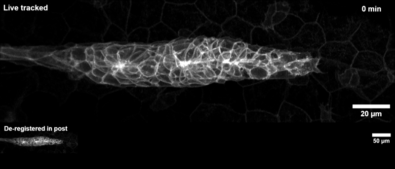
The zebrafish posterior lateral line primordium is a group of embryonic cells in fish and amphibia that undergo collective cell migration over a large distance along the embryo’s flank, periodically depositing clusters of cells that develop into sensory organs, so-called neuromasts. Because of its coherent long-range migration behavior, the lateral line primordium is an ideal use case for DySTrack (and indeed inspired the development of the first DySTrack prototype).
The lateral line pipeline employs Gaussian smoothing and object-count thresholding to find a foreground mask, then retains only the largest object therein (the primordium itself). The new coordinates for z and y are the centers of mass for this mask, whereas the new x-coordinate is calculated based on the leading edge such that migratory movement is anticipated.
Convention
By convention, pipelines assume that embryos are mounted with the anterior to the left, so the leading edge of the primordium is on the right of the image.
For details on the function’s call signature, see the API reference.
Tracking regression of the chick Hensen’s node#
The organizer of chick gastrulation, Hensen’s node, regresses caudally through the primitive streak as gastrulation proceeds. This pipeline is used to track the node based on electroporated labeling and to image cells that leave the node toward the anterior.
Here’s an example of a resulting time course (maximum z-projected and downsampled in space and time to limit file size):

The chick node pipeline uses a different approach to find coordinates that is not based on foreground masking. Instead, it defines simple models of expected instensity profiles along each axis, then fits these models to the observed intensity profiles, and finally uses parameters of the models as new coordinates.
Convention
By convention, pipelines assume that embryos are mounted with the anterior to the left, so the node regresses toward the right and labeled cells leave the node toward the left.
For details on the function’s call signature, see the API reference.
Minimal example pipeline#
This is a simplistic minimal example that simply tracks the center of mass of intensity in the image. It is useful as a didactic example and simple starting point for users looking to develop their own pipelines. For actual center-of-mass tracking applications, we recommend using the more full-featured center-of-mass pipeline described above.
For details on the function’s call signature, see the API reference.